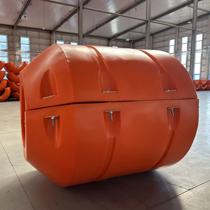
Custom Pipeline Float For Subsea Tie-In And Controlled Positioning Products, Quotes
Product Description
Contact Us
We are committed to providing you with the best quality service and look forward to communicating with you to solve problems together and bring you a better experience.
-
 Phone: +86-158-6665-7686
- WhatsApp: +86-158-6665-7686
-
 E-mail: [email protected]




Product Features
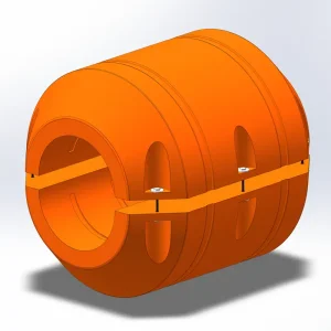
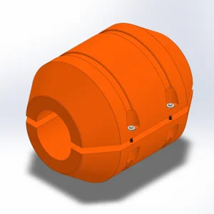
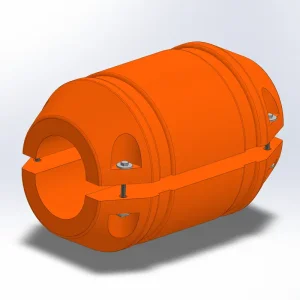
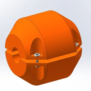
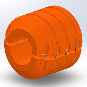
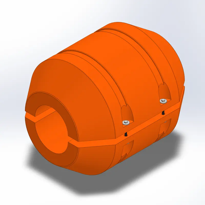
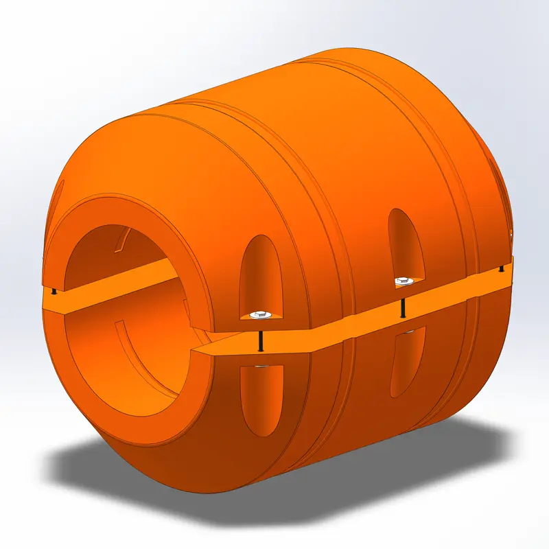
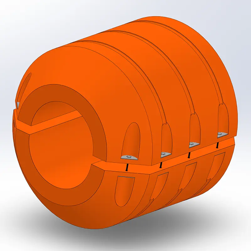
- Modular Buoyancy Configuration: Combine buoyancy modules to meet the support requirements of different pipeline sections, subject to the approved installation design.
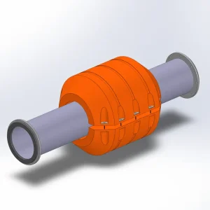
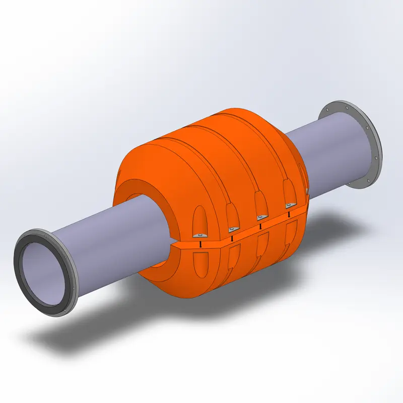
- Subsea Installation Support: Provides temporary flotation assistance during deployment, positioning, and underwater tie-in operations.
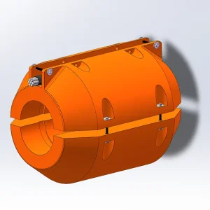
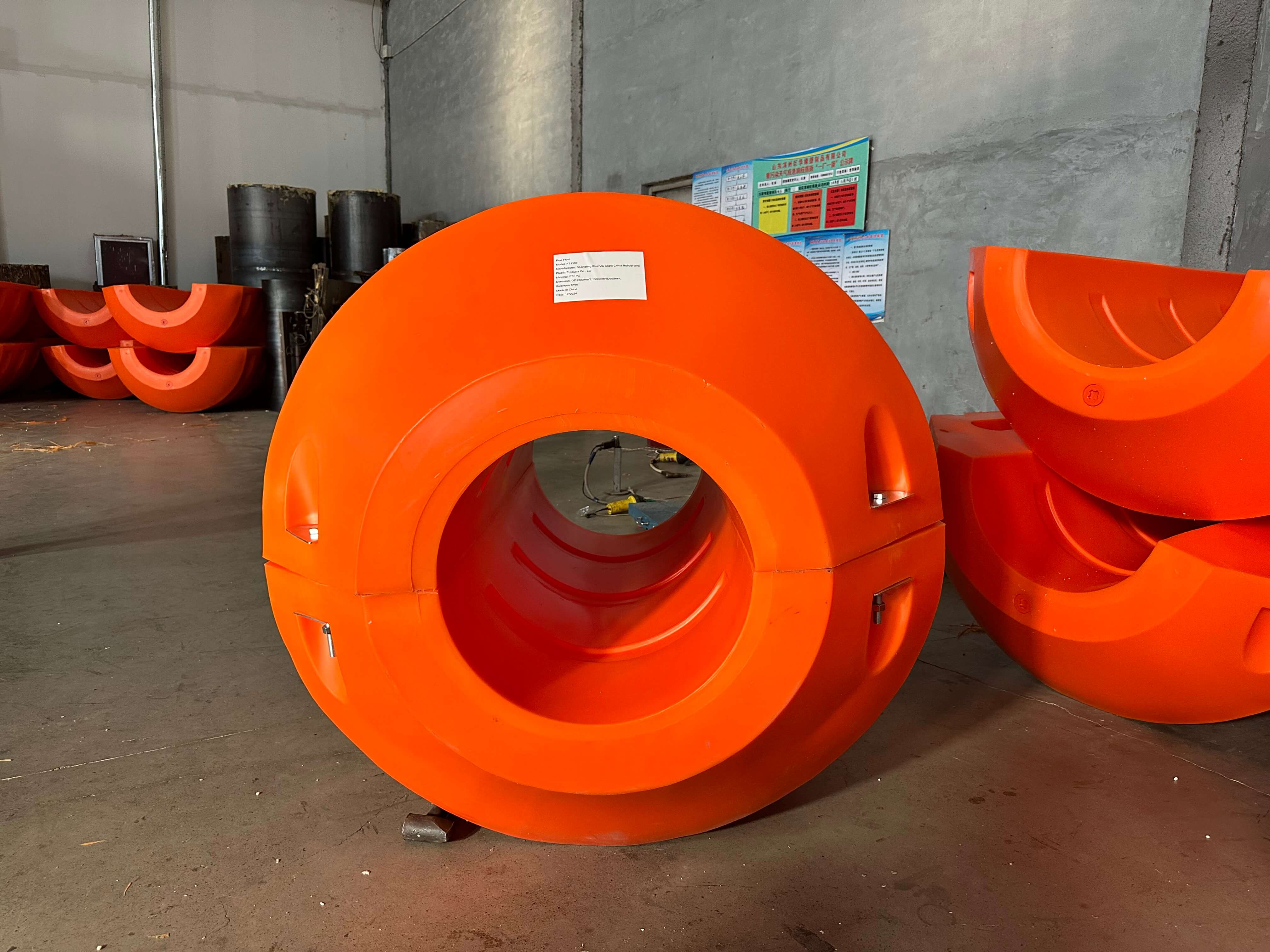
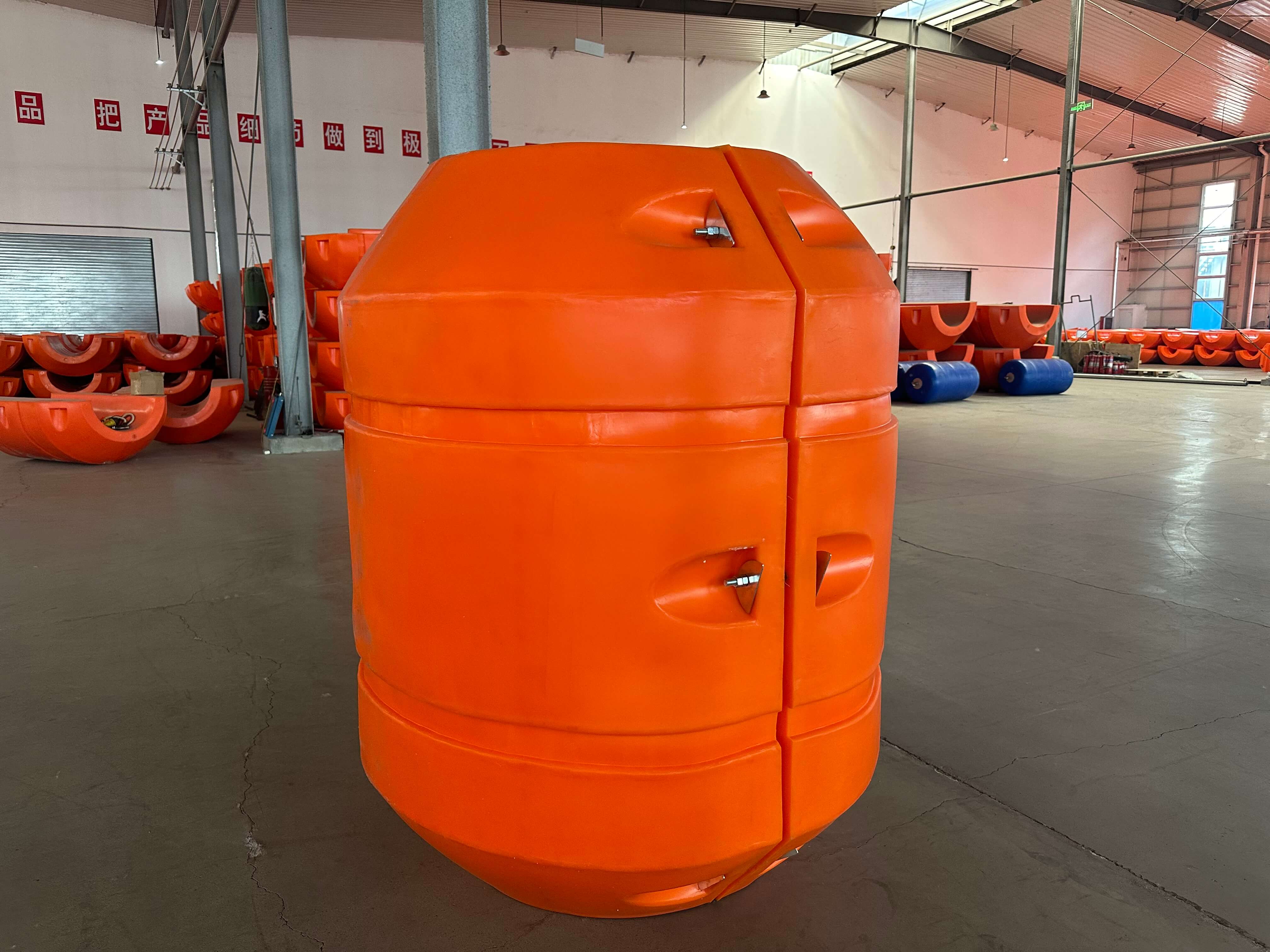
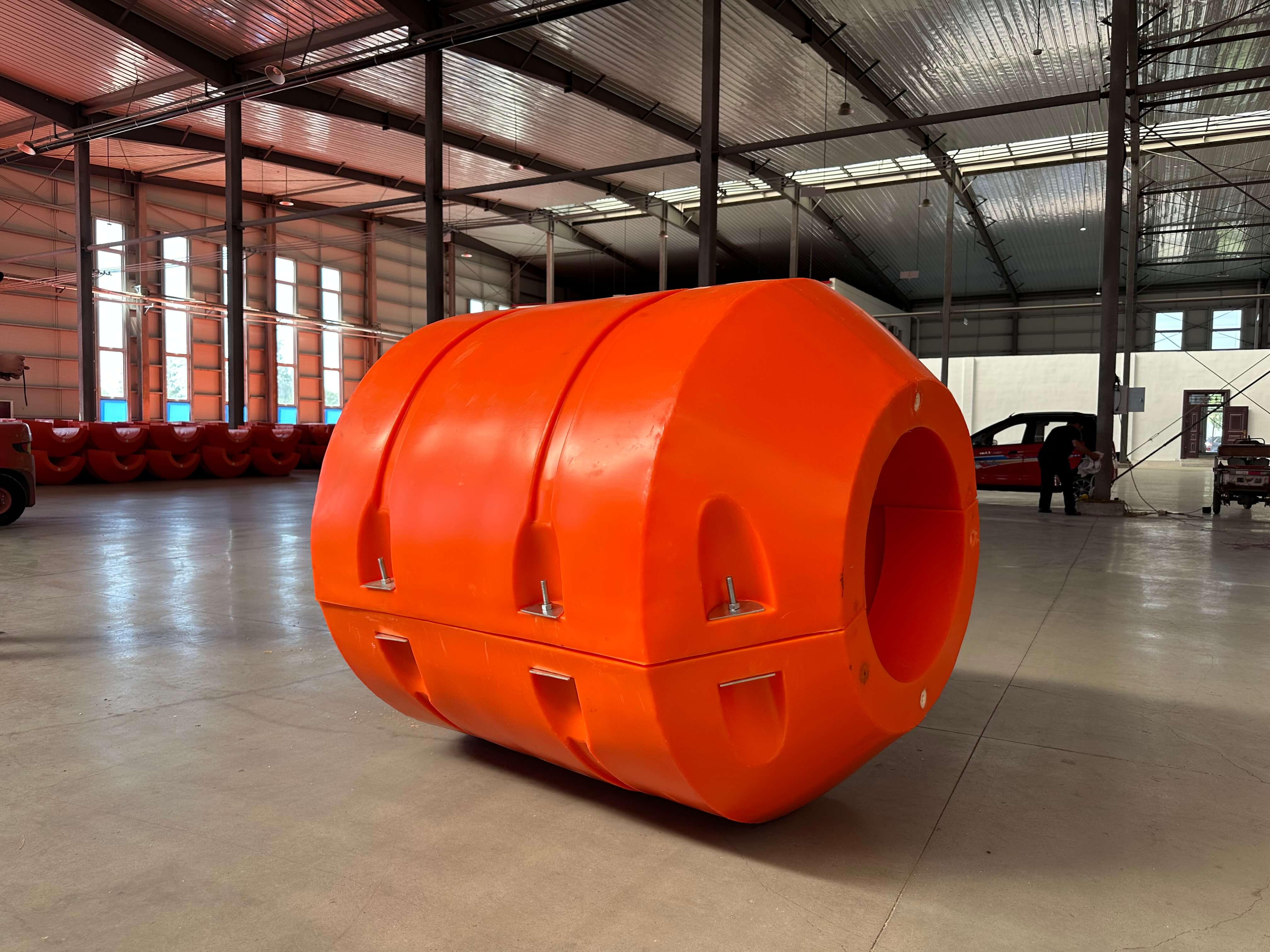
- Multiple Attachment Options: Select steel straps, steel-textile composite straps, or project-specific polymer straps according to pipe surface and installation requirements.
- Reference Module Dimensions: Standard dimensions of 1950 × 1100 × 1150 mm provide a baseline for handling, logistics, and planning.
- Depth-Specific Configuration: Published range covers 10–300 m. Confirm the operating depth rating and buoyancy performance prior to deployment.
- Adjustable Module Quantity: Vary the quantity based on pipeline submerged weight and engineering load calculations.
- Project-Specific Pipe Compatibility: Attachment arrangements can be matched with pipe outside diameter, surface coating, and geometric configurations.
- Installation & Recovery Planning: Coordinate mounting access and removal procedures securely before offshore operations commence.
Product Detail 1
Product Detail 2
Product Detail 3
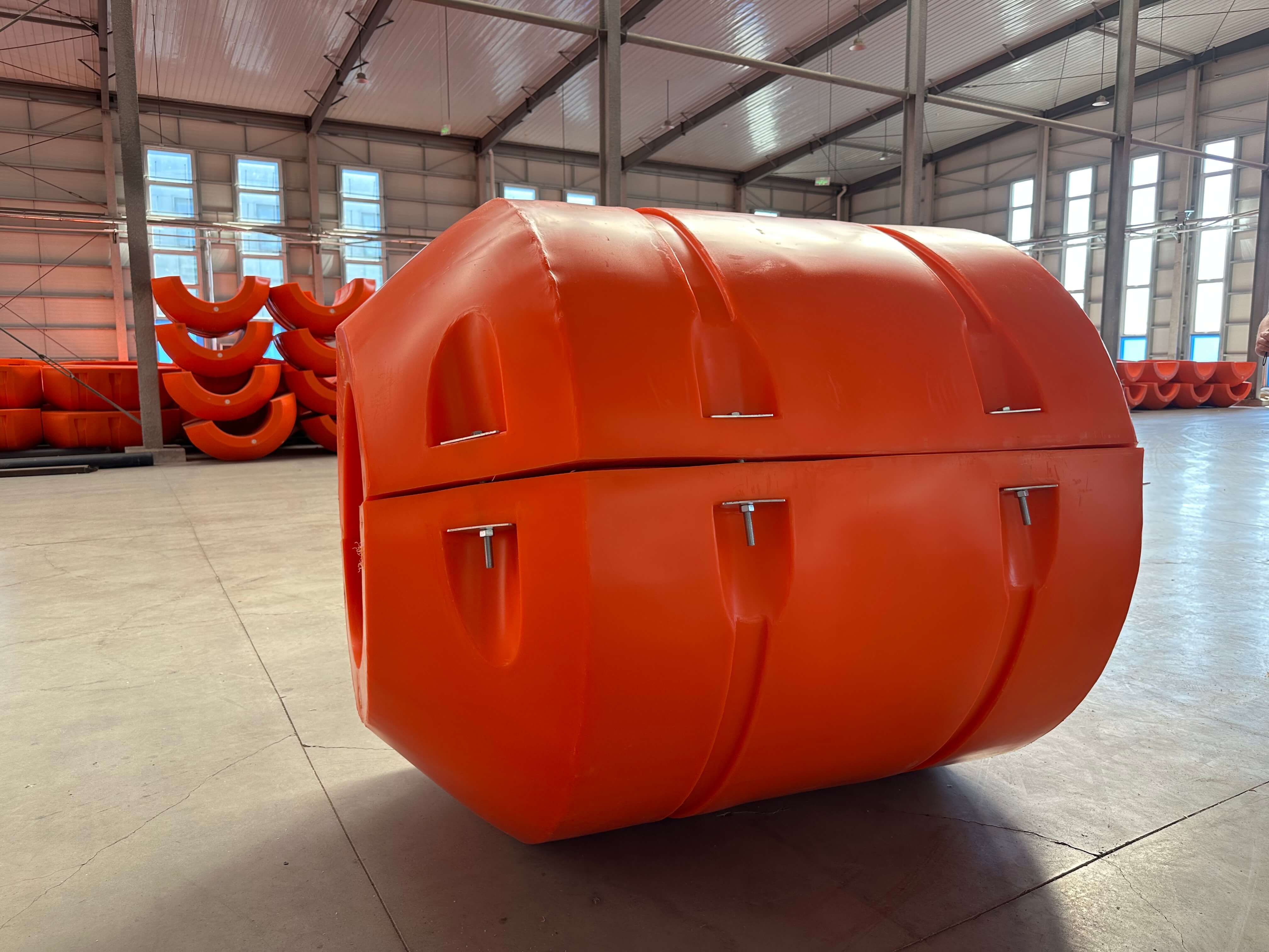
Product Detail 4
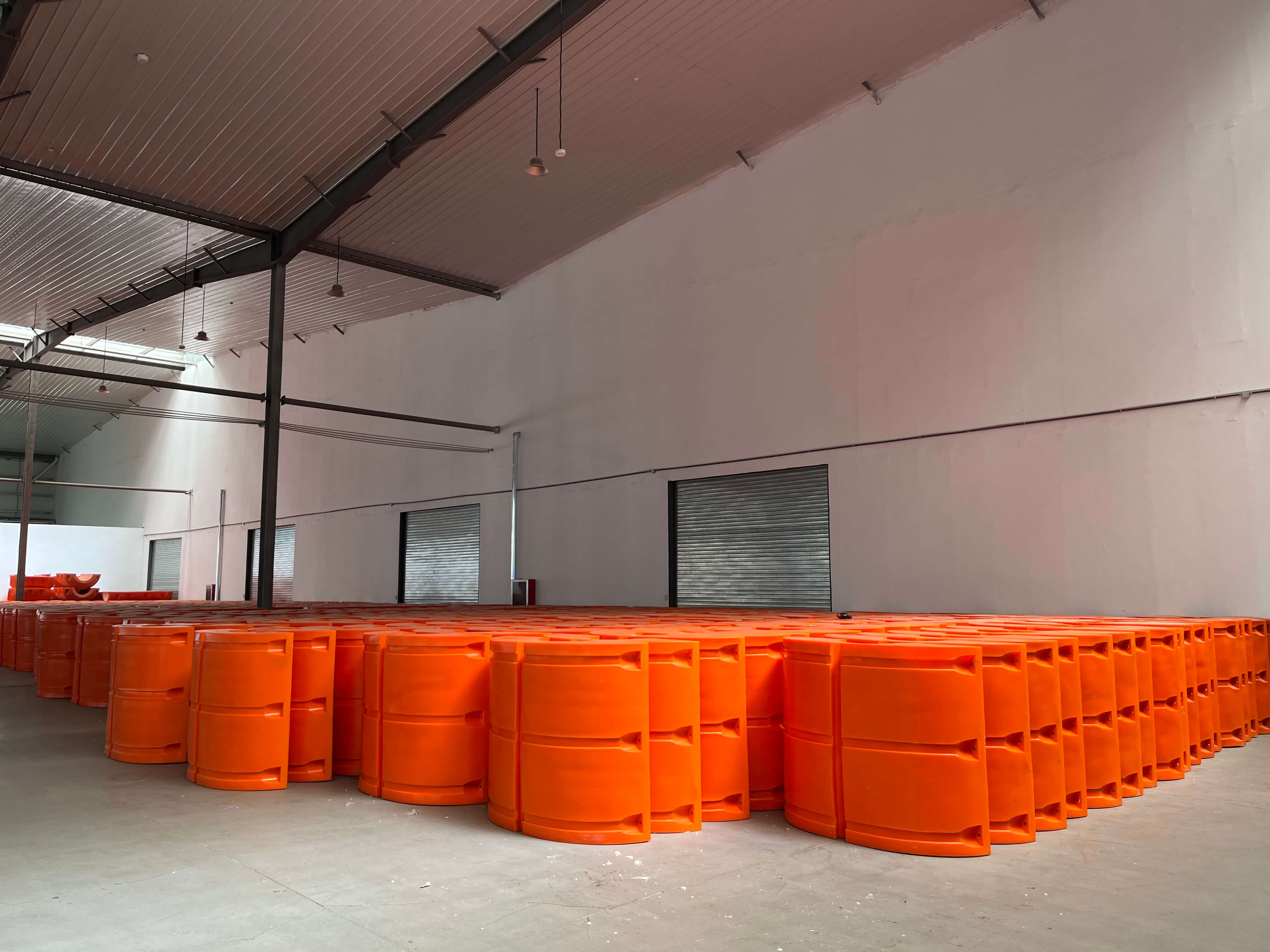
Product Detail 5
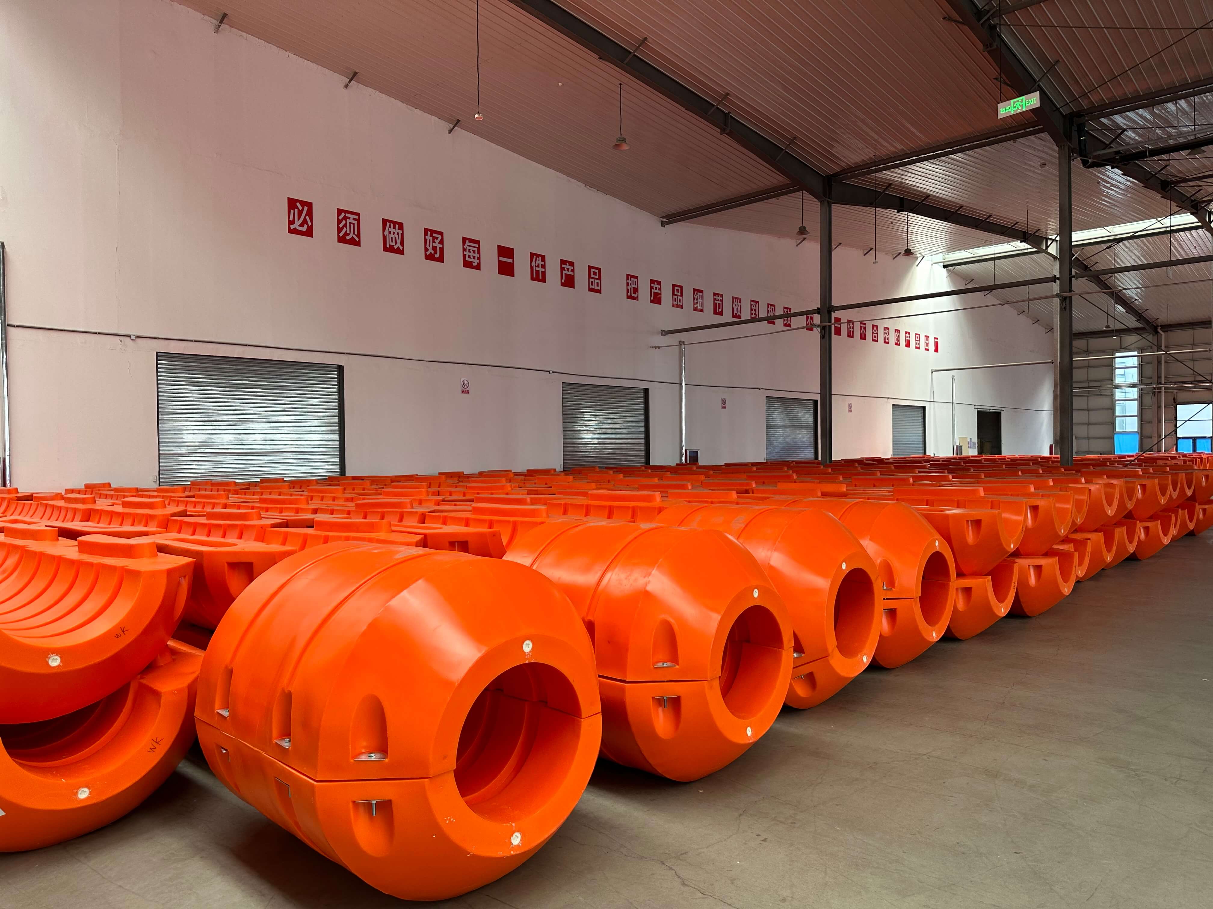
Product Detail 6
Pipe Floats Technical Specifications
| Model | Internal Diameter (mm) | External Diameter (mm) | Length (mm) | Wall Thickness (mm) | Net Buoyancy (kg) |
|---|---|---|---|---|---|
| FT500*500 | 110 | 500 | 500 | 5 | 150 |
| FT600*700 | 220/250 | 600 | 700 | 5 | 220 |
| FT500*800 | 160/180/200/220 | 500 | 800 | 5 | 240 |
| FT700*900 | 280 | 700 | 900 | 5 | 450 |
| FT800*1000 | 315 | 800 | 1000 | 6 | 550 |
| FT800*1100 | 400/350 | 800 | 1100 | 6 | 600 |
| FT1000*1000 | 325/350 | 1000 | 1000 | 6 | 650 |
| FT1100*1100 | 380/400/450 | 1100 | 1100 | 6 | 850 |
| FT1200*1200 | 430/450/500 | 1200 | 1200 | 7 | 1200 |
| FT1300*1300 | 480/500/560 | 1300 | 1300 | 7 | 1500 |
| FT1300*1500 | 530/560/630/610/660 | 1300 | 1500 | 8 | 1700 |
| FT1400*1500 | 560 | 1400 | 1500 | 8 | 1900 |
| FT1300*1600 | 560 | 1300 | 1600 | 8 | 2000 |
| FT1400*1600 | 630 | 1400 | 1600 | 8 | 2100 |
| FT1500*1800 | 660/680/710 | 1500 | 1800 | 9 | 2450 |
| FT1500*1850 | 670/680/650/720 | 1500 | 1850 | 9 | 2500 |
| FT1600*1900 | 730 | 1600 | 1900 | 9 | 2900 |
| FT1700*2000 | 780/810 | 1700 | 2000 | 9 | 2900 |
| TF1850*2100 | 840 | 1850 | 2100 | 10 | 3400 |
| FT2000*2400 | 900 | 2000 | 2400 | 12 | 4800 |
| FT2040*2500 | 940 | 2040 | 2500 | 13 | 5000 |
| FT2100*2500 | 1040/1050/1200 | 2100 | 2500 | 13 | 5500 |
| FT2300*2500 | 1150/1200 | 2300 | 2500 | 14 | 6500 |
Application Scenarios
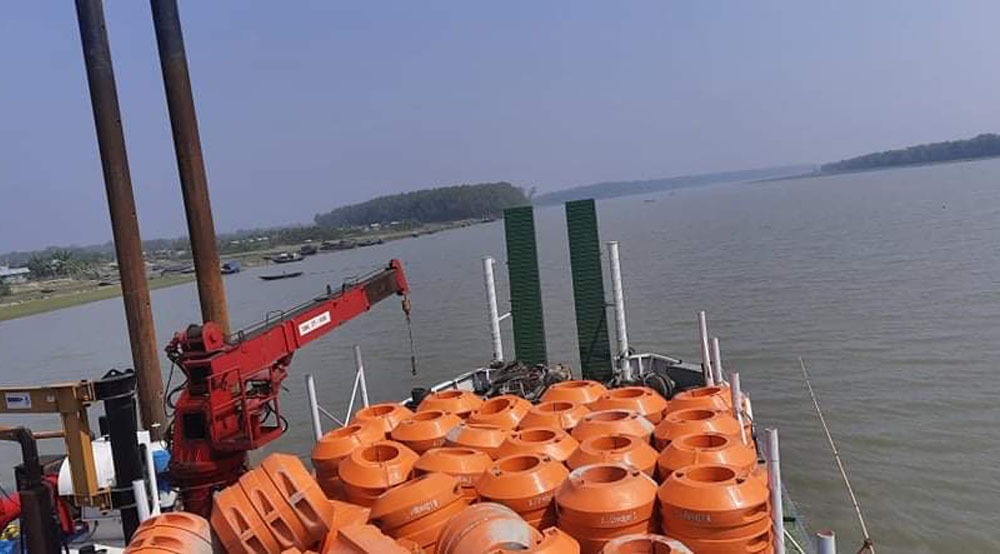
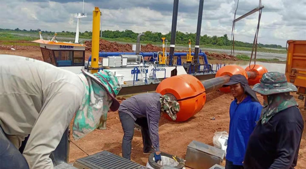
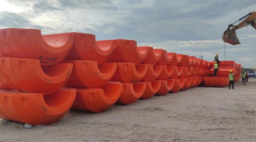
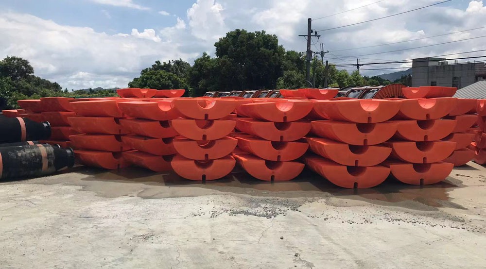
You may need different levels of buoyancy along a subsea pipeline, particularly when the installation involves varying pipe geometry or changes in the planned support arrangement.
A modular pipeline buoyancy system allows you to combine individual units into a project-specific configuration. This is ideal when the required buoyant force cannot be provided by a single module or when buoyancy must be distributed between designated positions.
Confirm the permitted module arrangement, total net buoyancy at depth, and resulting pipeline loads prior to deployment. Pipeline drawings and technical requirements can be submitted for dedicated configuration review.
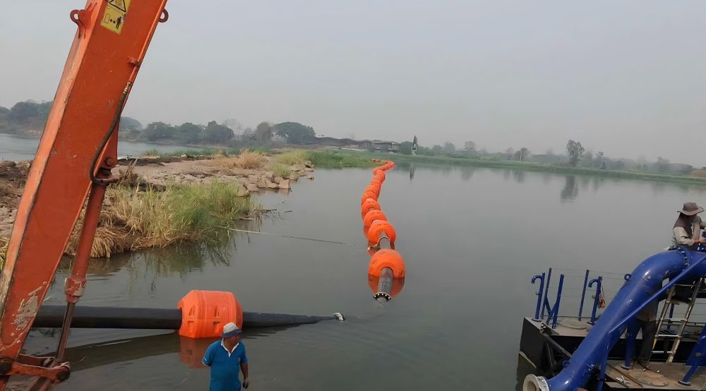
Application Scenario 1
Application Scenario 2
Application Scenario 3
Application Scenario 4
Application Scenario 5
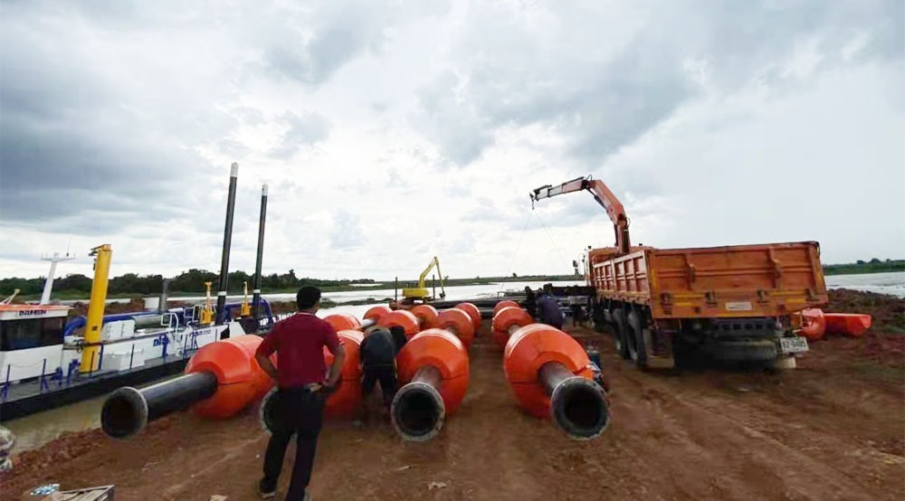
Application Scenario 6
Suitable Industries
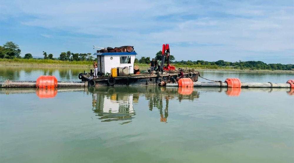
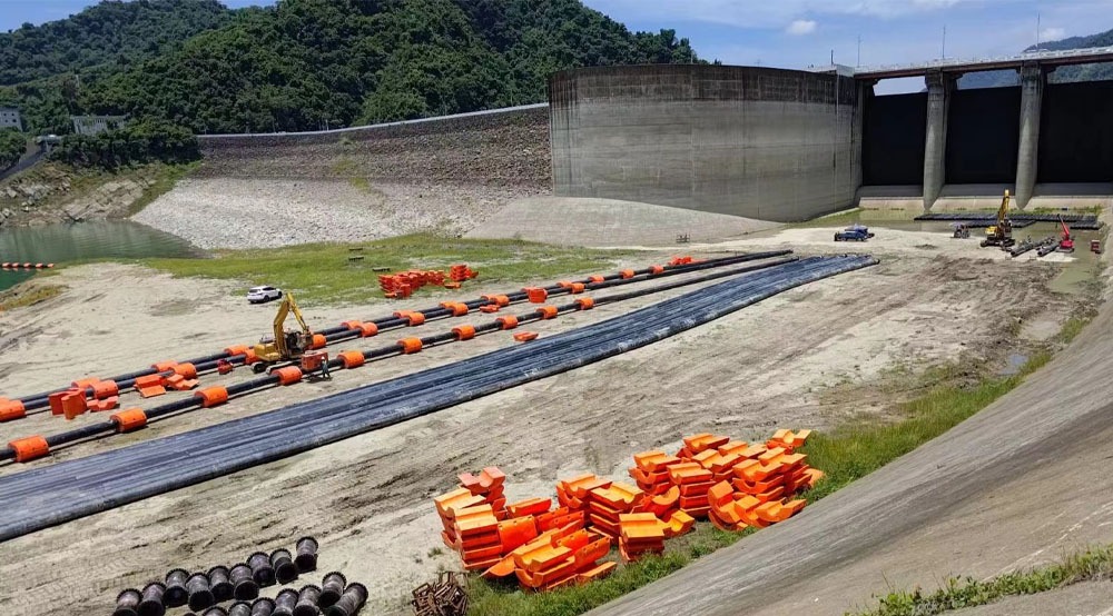
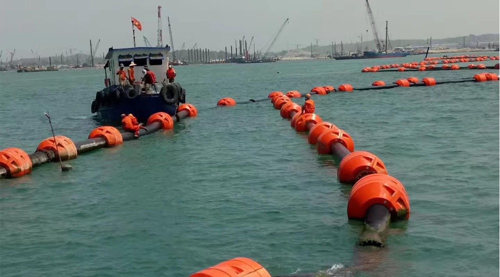
Use Pipeline Floats for underwater pipeline deployment, pipe positioning, offshore tie-in activities, and temporary support operations associated with marine construction.
For offshore energy projects, temporary buoyancy provides essential support when sections must be stabilized during an approved installation sequence or pull-in operation.
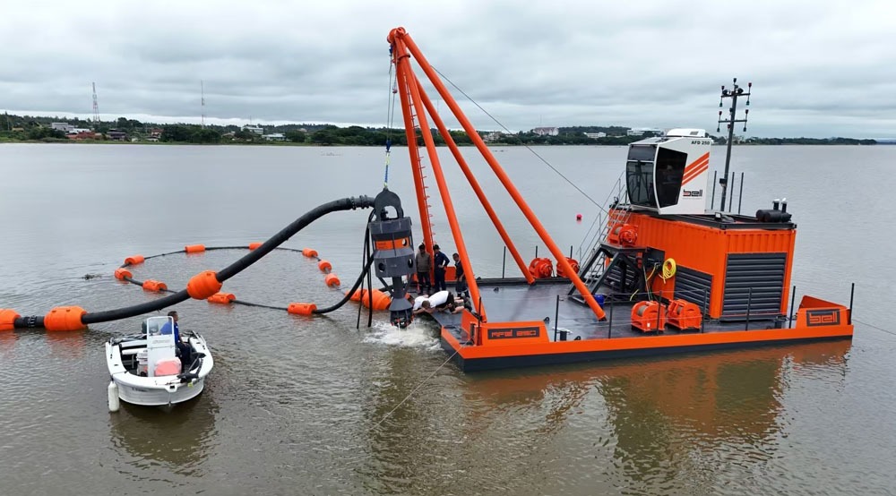
Suitable Industry 1
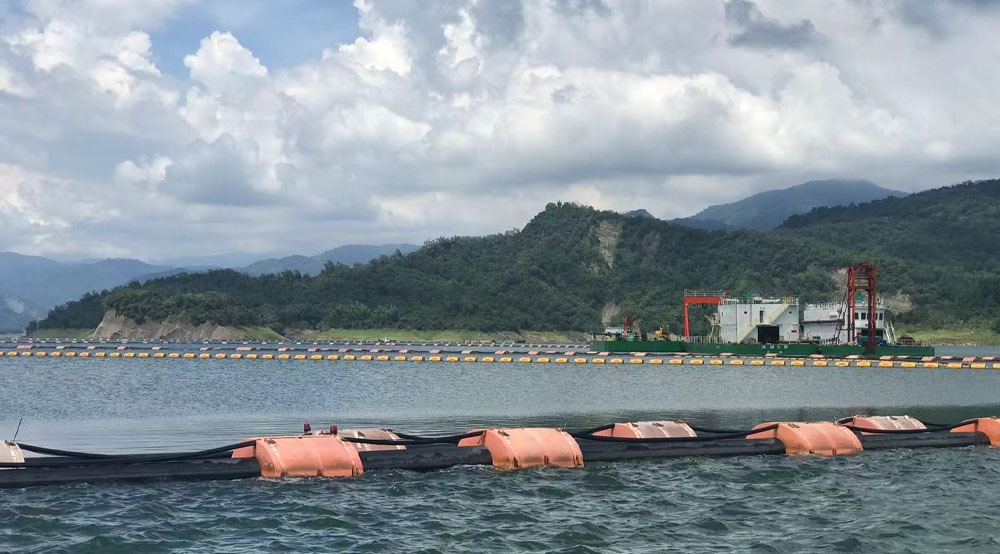
Suitable Industry 2
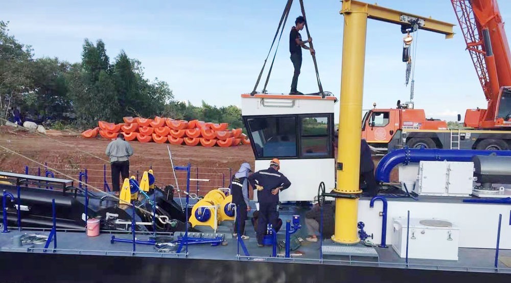
Suitable Industry 3
Suitable Industry 4
Suitable Industry 5
Suitable Industry 6
Qualification Certificate
Certificate 1
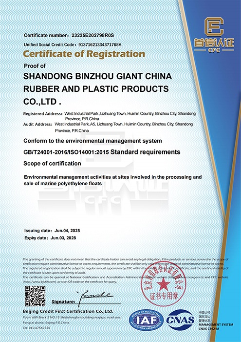
Certificate 2
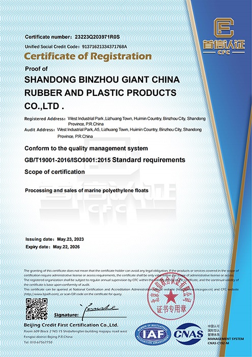
Certificate 3
Why Choose Giant Rubber?
Over 15 Years Experience
More than 15 years in flotation manufacturing, trusted by marine and water projects worldwide.
Strict Quality Assurance
Every product passes rigorous testing to ensure structural strength, durability, and high UV resistance.
Customized Engineering Solutions
Tailor-made flotation systems for dredging, aquaculture, navigation, and environmental projects.
Fast Global Delivery
Efficient logistics networks and direct factory supply guarantee reliable on-time worldwide delivery.
Continuous Innovation in Design
Advanced R&D ensures modern, reliable, and eco-friendly flotation engineering solutions.
Dedicated Customer Support
Professional service from project design to after-sales, ensuring smooth and dependable cooperation.

Custom Design

Quality Assurance

Technical Support

Fast Delivery

Maintenance Guidance

After-Sales Service
Frequently Asked Questions (FAQ)
A1: Of course. We have a professional design team that can design products according to client specifications, including custom dimensions, special controls, and OEM services.
A2: You need to ensure total buoyancy exceeds total weight. Calculate the combined weight of the pipe itself plus internal material (e.g., slurry or water) and accessories. The floats should provide at least 20–30% reserve buoyancy above the total weight to maintain proper floating stability.
A3: All floats feature high-grade Polyethylene (PE) plastic shells filled with closed-cell polyurethane foam for safety and structural rigidity. The tough PE outer shell withstands high impacts, and the foam core prevents sinking in the event of surface puncture.
A4: Yes, absolutely. Polyethylene (PE) is highly resistant to saltwater corrosion, UV radiation, and marine chemical degradation. They are preferred over steel floats in offshore environments because they never rust.
A5: Multiple attachment solutions can be selected based on pipeline surface properties and handling requirements, including galvanized or stainless steel straps, composite steel-textile straps, and custom polymer straps.
A6: Standard configurations support operational depths ranging from 10 m up to 300 m. Specific module configurations should be matched against load depth ratings before deployment.